ISD1600 SERIES
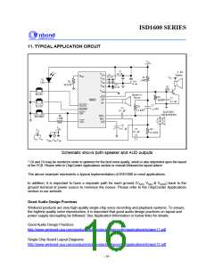
11. TYPICAL APPLICATION CIRCUIT
VCC
C2
8
Speaker
Ω
µ
0.1
F
VCCD
C3
0.1
ROSC
µ
F
R1
1 K
VCC
VCCA
VSSD
VSSA
DI
LED
Ω
R2
C8 *
µ
F
10
C9 *
80 K Ω
Q1
8050
µ
10
F
VSSAD
PLAYL
Speaker or
Buzzer
AUD
SP+
R5
C7
0.1
I1800
1600
390
Ω
F
µ
SP-
C1
PLAYL
PLAYE
REC
PLAYE
R3
C4
0.1
µ
4.7
F
4.7 K
Ω
F
µ
ELECTRET
MICROPHONE
R6
1 K
MIC+
MIC -
AGC
RECORD
Ω
LED
C6
4.7
VSS
F
µ
C5
R4
4.7 K
VCC
0.1
F
µ
Ω
VCCD VCCA
VSSAD VSSA VSSD
Schematic shows both speaker and AUD outputs
* C8 and C9 may be needed in order to optimize for the best voice quality, which is also depended upon the layout
of the PCB. Please refer to ChipCorder Applications section or consult Winbond for layout advice.
The above example represents a typical implementation of ISD1600 in most applications.
In addition, it is important to have a separate path for each ground (VSSD, VSSA & VSSAD) back to the
ground terminal of power source to minimize the noises. Please refer to the ChipCorder Applications
section in our website.
Good Audio Design Practices
Winbond products are very high-quality single-chip voice recording and playback systems. To ensure
the highest quality voice reproduction, it is important that good audio design practices on layout and
power supply decoupling be followed. See Application Information or below links for details.
Good Audio Design Practices
http://www.winbond-usa.com/products/isd_products/chipcorder/applicationinfo/apin11.pdf
Single-Chip Board Layout Diagrams
http://www.winbond-usa.com/products/isd_products/chipcorder/applicationinfo/apin12.pdf
- 16 -

 WINBOND [ WINBOND ]