ISD1600 SERIES
7.2. Functional Description Example
The following example operating sequences demonstrate the functionality of the ISD1600 series.
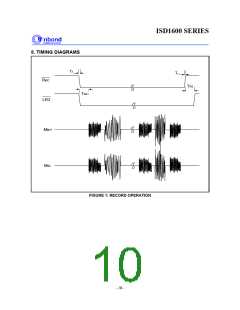
1. Record a message
The device starts recording from the beginning of the memory when REC transits from HIGH to LOW
and stays at LOW. A record cycle is completed when REC is pulled to HIGH or entire memory is filled
up. Then an End-of-Message (EOM) marker is written at the end of message, enabling a subsequent
playback cycle to terminate appropriately. Hence, the device automatically enters into standby mode.
REC takes precedence over any playback operations. If REC is pulled LOW during a playback cycle,
the playback immediately halts and recording starts from the beginning of the memory.
The REC pin has an internal pull-up device[2]. Holding this pin LOW after recording cycle will increase
standby current consumption.
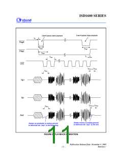
2. Edge-trigger playback
A playback operation starts from the beginning of the memory when PLAYE detects a LOW going
signal exceeding the specified debounced time. Playback continues until an EOM marker is
encountered. Upon completion of a playback cycle, the device automatically powers down and enters
into standby mode.
During playback, a subsequent LOW going signal will terminate the current playback operation.
This pin has an internal pull-up device[2]. Holding this pin LOW after playback operation will increase
standby current consumption.
3. Level- trigger playback
When PLAYL switches from HIGH to LOW and stays at LOW, a playback starts from the beginning of
the memory until either an EOM marker is reached, then it automatically powers down.
If PLAYL is pulled HIGH any time during playback, the playback operation stops immediately and the
device enters into the power-down mode.
4. LED operation
The LED output pin provides an active-LOW signal during recording, which is used to turn on an LED
as a “record-in-progress” indicator. However, during playback, the LED blinks a few times per second
to indicate a “playback-in-progress” operation. It returns to a HIGH state when operation stops.
5. ROSC operation
The duration of the device can be varied by changing the value of ROSC. This means the designer has
the flexibility to choose different sampling frequency, up to 12 KHz, depending upon the needs.
This feature allows frequency shifting where a recorded audio can be played back faster or slower
than normal for special sound effects.
Another feature is a “Pause” function that can be activated by taking the ROSC resistor to VCC to stop
playback momentarily, and to resume when the resistor is switched back to ground.
Publication Release Date: November 4, 2004
- 9 -
Revision 1

 WINBOND [ WINBOND ]