24C02/04/08/16
will be overwritten.
ACKNOWLEDGE POLLING: Once the internally timed write cycle has started and the EEPROM inputs
are disabled, acknowledge polling can be initiated. This involves sending a start condition followed by the
device address word. The read/write bit is representative of the operation desired. Only if the internal
write cycle has completed will the EEPROM respond with a "0", allowing the read or write sequence to
continue.
ꢀRead Operations
Read operations are initiated the same way as write operations with the exception that the read/write
select bit in the device address word is set to "1". There are three read operations: current address read,
random address read and sequential read.
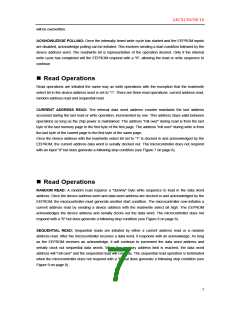
CURRENT ADDRESS READ: The internal data word address counter maintains the last address
accessed during the last read or write operation, incremented by one. This address stays valid between
operations as long as the chip power is maintained. The address "roll over" during read is from the last
byte of the last memory page to the first byte of the first page. The address "roll over" during write is from
the last byte of the current page to the first byte of the same page.
Once the device address with the read/write select bit set to "1" is clocked in and acknowledged by the
EEPROM, the current address data word is serially clocked out. The microcontroller does not respond
with an input "0" but does generate a following stop condition (see Figure 7 on page 8).
ꢀRead Operations
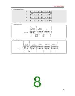
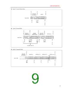
RANDOM READ: A random read requires a "dummy" byte write sequence to load in the data word
address. Once the device address word and data word address are clocked in and acknowledged by the
EEPROM, the microcontroller must generate another start condition. The microcontroller now initiates a
current address read by sending a device address with the read/write select bit high. The EEPROM
acknowledges the device address and serially clocks out the data word. The microcontroller does not
respond with a "0" but does generate a following stop condition (see Figure 8 on page 8).
SEQUENTIAL READ: Sequential reads are initiated by either a current address read or a random
address read. After the microcontroller receives a data word, it responds with an acknowledge. As long
as the EEPROM receives an acknowledge, it will continue to increment the data word address and
serially clock out sequential data words. When the memory address limit is reached, the data word
address will "roll over" and the sequential read will continue. The sequential read operation is terminated
when the microcontroller does not respond with a "0" but does generate a following stop condition (see
Figure 9 on page 8).
7

 TGS [ Tiger Electronic Co.,Ltd ]