DS_8430_001
78Q8430 Data Sheet
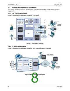
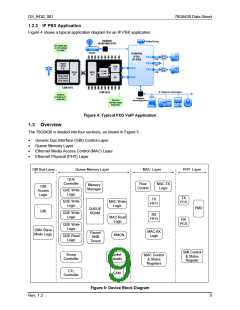
1.2.3 IP PBX Application
Figure 4 shows a typical application diagram for an IP PBX application.
78Q8430
10/100 MAC/PHY
78Q8430
10/100 MAC/PHY
Figure 4: Typical FXO VoIP Application
1.3 Overview
The 78Q8430 is divided into four sections, as shown in Figure 5.
•
•
•
•
Generic Bus Interface (GBI) Control Layer
Queue Memory Layer
Ethernet Media Access Control (MAC) Layer
Ethernet Physical (PHY) Layer
GBI Bus Layer
Queue Memory Layer
MAC Layer
PHY Layer
QUE
Controller
Flow
Control
MAC TX
Logic
Memory
Manager
GBI
Access
Logic
QUE Write
Logic
TX
PCS
TX
FIFO
QUE Write
Logic
MAC Write
Logic
PMD
QUEUE
SRAM
GBI
QUE Write
Logic
RX
FIFO
MAC Read
Logic
RX
PCS
QUE Write
Logic
DMA Slave
Mode Logic
MAC RX
Logic
Pause/
HNR
Timers
RMON
QUE Read
Logic
SMI Control
& Status
Register
Snoop
Controller
Packet
Classify
MAC Control
& Status
Registers
CTL
Controller
CAM
Figure 5: Device Block Diagram
Rev. 1.2
9

 TERIDIAN [ TERIDIAN SEMICONDUCTOR CORPORATION ]