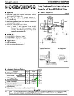
Hologram Lasers
GH6D307B5A/GH6D307B5B
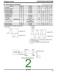
■ Electro-optical Characteristics of Laser Diode (Design Standard)
(TC=25˚C)
Parameter
Symbol
Conditions
MIN.
7
TYP.
MAX.
11
Unit
θ//
θ
Parallel
Perpendicular
Parallel
-
-
-
-
-
-
-
-
˚
Half intensity angle
26
35
˚
Po=3mW
ø//
ø
-2.1
-3
+2.1
+3
˚
Emission
Deviation
angle
characteristics
Perpendicular
˚
∆x
∆y
∆z
α
µm
µm
µm
-
-80
-80
-80
-
+80
+80
+80
1
−
Misalignment position
■6
Interference pattern intensity
Po=3mW
■ Electrical Characteristics of Monitor Photodiode (Design Standard)
(TC=25˚C)
Parameter
Symbol
Conditions
MIN.
TYP.
0.02
-
MAX.
Unit
mA/ mW
nA
■1
Sensitivity
S
-
-
-
-
150
-
Dark current
ID
Ct
VR=15V
Terminal capacitance
3.5
pF
■1
For hologram output power
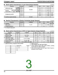
■ Electro-optical Characteristics of OPIC for Signal Detection (Design Standard)
(TC=25˚C)
■2
Segment
Parameter
Supply voltage
Symbol
VCC
Conditions
MIN.
4.5
2.25
6
TYP.
MAX.
5.5
2.75
16
Unit
V
−
5.0
2.5
-
-
Reference voltage
Supply current
Vs
Vs=1/ 2Vcc
VCC=5V
V
-
ICC
mA
mA
mV
MHz
dB
-
■3
Output off-set voltage
Off-set voltage difference
Response frequency
Peaking level
VOD
∆VOD
fCF
-30
-30
40
0
+30
+30
-
VA, VB, VE, VF
VCC=5V, no light
0
VA-VB, VE-VF
■4
■5
VCC=5V, -3dB
-
VA, VB, VE, VF
VA, VB, VE, VF
VPK
f=0.1 to 20MHz, BW=10kHz
-2
-
+2
■2
■3
Applicable divisions correspond to output terminals
Difference from Vs
■4
■5
Output amplitude=0dB (input signal 100kHz)
Segment No.
D5
Output
Output amplitude=0dB (input signal 100kHz), peaking
characteristics from 100kHz to 20MHz.
D 1 + D 3 .....................................VA
D 2 + D 4 .....................................VB
D1
D2
D3
D4
D6
■6
Noise solution against feed-back ligh t (Radio frequency
modulation circuit) is required.
D 5 ...............................................VE
D 6 ...............................................VF
54

 SHARP [ SHARP ELECTRIONIC COMPONENTS ]