ZULU
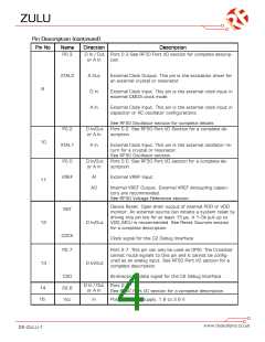
Pin Description (continued)
Pin No
17
Name
P2.5
Direction
Description
D In / Out
or A In
Port 2.5.
See RF50 Port I/O section for a complete description.
D In / Out
or A In
Port 2.4.
18
19
20
P2.4
P2.3
P2.2
See RF50 Port I/O section for a complete description.
D In/Out
or A In
Port 2.3. See RF50 Port I/O section for a complete de-
scription.
D In/Out
or A In
Port 2.2. See RF50 Port I/O section for a complete de-
scription.
21
22
XTAL4
XTAL3
AO
SmaRTClock Oscillator Crystal Output.
SmaRTClock Oscillator Crystal Input.
A in
D In/Out
or A In
Port 2.1.
23
24
P2.1
P2.0
See RF50 Port I/O section for a complete description.
D In/Out
or A In
Port 2.0.
See RF50 Port I/O section for a complete description.
D In/Out
or A In
Port 1.7.
25
26
27
P1.7
P1.6
P1.5
See RF50 Port I/O section for a complete description.
D In/Out
or A In
Port 1.6.
See RF50 Port I/O section for a complete description.
D In/Out
or A In
Port 1.5.
See RF50 Port I/O section for a complete description.
RF22 peripheral interrupt status pin. Will be set low to
indicate a pending RF22 interrupt event. See the RF22
Control Logic Registers for more details. This pin is an
open-drain output with a 220k internal pull-up resistor.
An external pull-up resistor is recommended.
28
NIRQ
D Out
AO RF22 peripheral crystal oscillator output. Connect to
an external 30 MHz crystal or leave floating if driving the
XIN pin with an external signal source.
29
30
XOUT
XIN
A Out
A in
RF22 peripheral crystal oscillator input. Connect to an
external 30 MHz crystal or to an external source. If us-
ing an external clock source with no crystal, dc coupling
with a nominal 0.8 VDC level is recommended with a
minimum ac amplitude of 700 mVpp.
DS-ZULU-1

 RFSOLUTIONS [ RFSOLUTIONS.LTD ]