SMART RADIO TRANSCEIVER
RF650
5 Technical Specifications
Electrical Characteristics
Min.
Typ.
Max.
Units
Notes
DC Levels
Supply voltage
1.9
11
3.3
3.6
30
V
mA
mA
uA
V
1
Supply current (Transmit mode)
Supply current (Receive mode)
Supply current (Standby mode)
Data input/output high
Data input/output low
12.5
125
Vcc–0.3
0
Vcc+0.3V
0.3
V
RF
Working frequency: 433MHz Module
868MHz Module
430.0
860
440.0
880.0
MHz
MHz
2
2
Receiver sensitivity
Transmitter RF power out
Frequency deviation
GFSK manchester encoded data rate
Operating temperature
Storage temperature
-100
+10
+/- 50
100
dBm
dBm
kHz
kbps
Deg C
Deg C
-20
-40
+80
+100
Dynamic Timing
Power up to stable receiver data out
Power up to full RF out
Standby to Receive mode
Standby to Transmit mode
30
30
1
mS
mS
mS
mS
1
Notes
1. Supply voltage should have <10mV ripple.
2. The application operating frequency must be chosen to comply with the Short Range device
regulation in the area of operation.
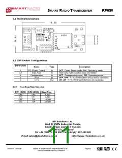
5.1 Mechanical Detail
Pin Pitch: 2.54mm
Module Pitch: 22.86mm
DS650-6 June ‘06
©2006 RF Solutions Ltd, www.rfsolutions.co.uk
Tel 01273 898000 Fax 01273 480661
Page 9

 RFSOLUTIONS [ RFSOLUTIONS.LTD ]