Product Brief
TransDimension
TD243
1
2
3
4
5
6
7
8
9 10
1
2
75
74
4
72
73
5
70
71
67
68
64
65
61
62
63
58
59
60
51
48
56
57
52
50
47
55
54
53
49
46
44
42
39
38
37
A
B
C
D
E
F
G
H
J
A
B
C
D
E
F
G
H
J
3
69 VSS 66
6
7
8
9
VDD VDD
12 10
11
14
16
17
18
VDD 45
VSS 43
13 VSS
15 VSS 23
26 VDD VSS 41
40
35
36
20
19
21
22
24
25
27
28
29
30
31
32
33
34
1
2
3
4
5
6
7
8
9 10
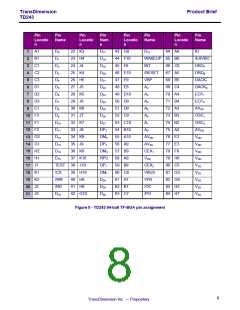
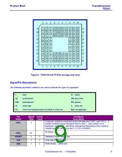
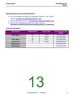
Figure 6 - TD243 84-ball TF-BGA package (top view)
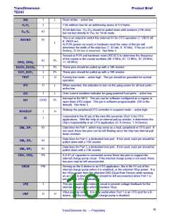
Signal/Pin Descriptions
The following shorthand notations are used to indicate the type of a signal/pin:
I:
input
O: output
IO:
PW:
H:
bi-directional
OD: open drain
PS: passive
power/ground
active high
L: active low
N/A: not applicable
PL:
active level programmable but default to active low
Pin
Signal Active
Pin/Signal
Name
OSC1
Type
Level
Description
A passive crystal is connected across the two pins (OSC1 and OSC2). A
crystal oscillator output should be tied to OSC2. Upon power-on or
hardware reset, DRQ1 and DRQ0 indicate the frequency of the crystal or
crystal oscillator, which can be 6, 12, 24 or 48 MHz.
I
As above.
IO
OSC2
/RESET
/CS
I
I
I
L
L
L
Hardware reset – active low.
Chip select – active low.
Write strobe – active low.
/WR
TransDimension Inc. — Proprietary
9

 OXFORD [ OXFORD SEMICONDUCTOR ]