KA
7500
Total Device
Parameter
Test conditions
Value
Unit
MIN
MIN
TYP**
MAX
10
Standby supply current
Pin 6 at Vref
Vcc=15V
6
mA
25oC
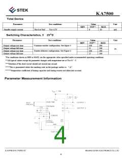
Switching Characteristics,
T
Parameter
Test conditions
Value
TYP**
100
Unit
MAX
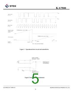
Output voltage rise time
Output voltage fall time
Output voltage rise time
Output voltage fall time
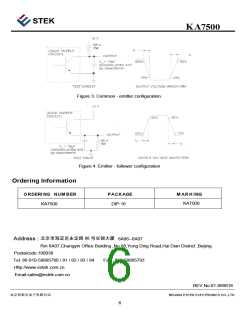
Common-emitter configuration, See figure 3
Emitter-follower configuration. See Figure 4
200
100
200
100
25
ns
100
25
*For conditions shown as MIN or MAX, use the appropriate value specified under recommended operating conditions.
**All typical values except for parameter changes with temperature are at TA=25
***Duration of the short-circuit should not exceed one second
°C
****This is guaranteed where the marking code on the package surface is
“A”
*****Temperature coefficient of timing capacitor and timing resistor not taken into account.
Parameter Measurement Information
BEIJING ESTEK ELECTRONICS CO.,LTD
4

 ESTEK [ Estek Electronics Co. Ltd ]