EN29LV160A
USER MODE DEFINITIONS
Word / Byte Configuration
The signal set on the BYTE# Pin controls whether the device data I/O pins DQ15-DQ0 operate in the
byte or word configuration. When the Byte# Pin is set at logic ‘1’, then the device is in word
configuration, DQ15-DQ0 are active and are controlled by CE# and OE#.
On the other hand, if the Byte# Pin is set at logic ‘0’, then the device is in byte configuration, and only
data I/O pins DQ0-DQ7 are active and controlled by CE# and OE#. The data I/O pins DQ8-DQ14
are tri-stated, and the DQ15 pin is used as an input for the LSB (A-1) address function.
Standby Mode
The EN29LV160A has a CMOS-compatible standby mode, which reduces the current to < 1µA
(typical). It is placed in CMOS-compatible standby when the CE# pin is at VCC ± 0.5. RESET# and
BYTE# pin must also be at CMOS input levels. The device also has a TTL-compatible standby mode,
which reduces the maximum VCC current to < 1mA. It is placed in TTL-compatible standby when the
CE# pin is at VIH. When in standby modes, the outputs are in a high-impedance state independent of
the OE# input.
Read Mode
The device is automatically set to reading array data after device power-up. No commands are
required to retrieve data. The device is also ready to read array data after completing an Embedded
Program or Embedded Erase algorithm.
After the device accepts an Erase Suspend command, the device enters the Erase Suspend mode.
The system can read array data using the standard read timings, except that if it reads at an address
within erase-suspended sectors, the device outputs status data. After completing a programming
operation in the Erase Suspend mode, the system may once again read array data with the same
exception. See “Erase Suspend/Erase Resume Commands” for more additional information.
The system must issue the reset command to re-enable the device for reading array data if DQ5
goes high, or while in the autoselect mode. See the “Reset Command” additional details.
Output Disable Mode
When the CE# or OE# pin is at a logic high level (VIH), the output from the EN29LV160A is disabled.
The output pins are placed in a high impedance state.
Auto Select Identification Mode
The autoselect mode provides manufacturer and device identification, and sector protection
verification, through identifier codes output on DQ15–DQ0. This mode is primarily intended for
programming equipment to automatically match a device to be programmed with its corresponding
programming algorithm. However, the autoselect codes can also be accessed in-system through the
command register.
When using programming equipment, the autoselect mode requires VID (10.5 V to 11.5 V) on
address pin A9. Address pins A6, A1, and A0 must be as shown in Autoselect Codes table. In
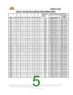
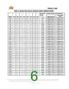
addition, when verifying sector protection, the sector address must appear on the appropriate highest
order address bits. Refer to the corresponding Sector Address Tables. The Command Definitions
table shows the remaining address bits that are don’t-care. When all necessary bits have been set as
required, the programming equipment may then read the corresponding identifier code on DQ15–
DQ0.
This Data Sheet may be revised by subsequent versions
or modifications due to changes in technical specifications.
©2004 Eon Silicon Solution, Inc., www.essi.com.tw
9
Rev. I, Issue Date: 2008/07/17

 ESMT [ ELITE SEMICONDUCTOR MEMORY TECHNOLOGY INC. ]