EM73P461A
4-BIT MICRO-CONTROLLER FOR LCD PRODUCT
(1)For instruction : LDL #k, LDH #k, THA, THL, INCL, DECL, EXAL, EXAH, HL register used as a
temporary register.
PROGRAM EXAMPLE: Load immediate data "5h" into L register, "Dh" into H register.
LDL#05h;
LDH#0Dh;
(2) For instruction LDAM, STAM, STAMI .., HL register used as a pointer for the address of RAM memory.
PROGRAM EXAMPLE: Store immediate data #Ah into RAM of address 35h.
LDL#5h;
LDH #3h;
STDMI #0Ah; RAM[35] ← Ah
(3) For instruction : SELP, CLPL, TFPL, L regieter be a pointer to indicate the bit of I/O port.
When LR = 0 indicate P4.0
PROGRAM EXAMPLE: To set bit 0 of Port4 to "1"
LDL#00h;
SEPL ; P4.0 ←1
STACK POINTER (SP)
Stack pointer is a 4-bit register which stores the present stack level number.
Before using stack, user must set the SP value first, CPU will not initiate the SP value after reset condition
. When a new subroutine is accepted, the SP will be decreased one automatically, in another word, if
returning from a subroutine, the SP will be increased one.
The data transfer between ACC and SP is by instruction of "LDASP" and "STASP".
DATA POINTER (DP)
Data pointer is a 12-bit register which stores the address of ROM can indicate the ROM code data
specified by user (refer to data ROM).
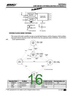
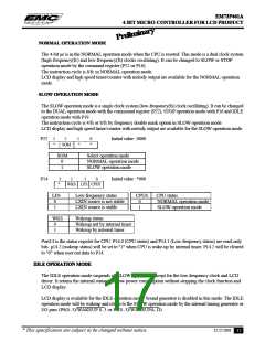
CLOCK AND TIMING GENERATOR
The clock generator is supported by a single clock system, the clock source comes from crystal (resonator)
or RC oscillation is decided by mask option, the working frequency range is 480 K Hz to 4 MHz depending
on the working voltage.
CLOCK GENERATOR STRUCTURE
There are two clock generator for system clock control. P14 is the status register for the CPU status. P16,
P19 and P22 are the system clock mode control ports.
* This specification are subject to be changed without notice.
12.27.2001
15

 ELAN [ ELAN MICROELECTRONICS CORP ]