EM73P361A
4-BIT MICRO-CONTROLLER FOR LCD PRODUCT
TIMER/COUNTER FUNCTION
Each timer/counter can execute the timer function independly.
TIMER MODE
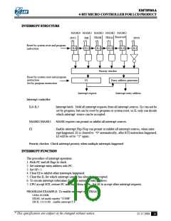
For timer mode ,timer/counter increase one at any rising edge of internal pulse . User can choose 4 kinds
of internal pulse rate by setting IPSB for timerB (IPSA for timerA).
When timer/counter counts overflow, TRGB (TRGA) will be generated to interrupt control unit.
Internal pulse
n
n+1
n+2
n+3
n+4
n+5
n+6
n+7
TimerB (TimerA )value
PROGRAM EXAMPLE: To generate TRGA interrupt request after 60 ms with system clock XlN=32K Hz
LDIA
#0100B;
EXAE; enable mask 2
EICIL 110111B; internupt latch ← 0, enable EI
LDIA
#04H;
STATAL;
LDIA
STATAM;
LDIA
STATAH;
LDIA
#0CH;
#0FH;
#1000B;
OUTA P28; enable timerA with internal pulse rate: XIN/25 Hz
NOTE: The preset value of timer/counter register is calculated as following procedure.
Internal pulse rate: XIN/25 ; XIN = 32KHz
The time of timer counter count one = 25 /XIN = 32/32K=1ms
The number of internal pulse to get timer overflow = 60 ms/ 1ms = 60 = 03CH
The preset value of timer/counter register = 1000H - 03CH = 0FC4H
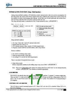
INTERRUPT FUNCTION
There are 3 internal interrupt sources and 2 external interrupt sources. Multiple interrupts are admitted
according the priority .
Type
Interrupt source
Priority Interrupt
Latch
Interrupt
Enable condition
Program ROM
entry address
External External interrupt (INT0)
Internal Reserved
Internal TimerA overflow interrupt (TRGA) 3
Internal TimerB overflow interrupt (TRGB) 4
Internal Time base interrupt(TBI)
External External interrupt (INT1)
1
2
IL5
IL4
IL3
IL2
IL1
IL0
EI=1
002H
004H
006H
008H
00AH
00CH
EI=1, MASK3=1
EI=1, MASK2=1
EI=1, MASK1=1
5
6
EI=1,MASK0=1
* This specification are subject to be changed without notice.
12.17.2001
15

 ELAN [ ELAN MICROELECTRONICS CORP ]