Applications Information: continued
will rise above the 1V level, preventing the FAULT latch
from being set, allowing normal operation to resume.
Trace1 - Regulator Output Voltage (1V/div.)
Trace 2 - Inductor Switching Node (5V/div.)
Trace 3 - Output Current (13 to 0.5 Amps) (20V/div.)
Trace 4 - 5V Supply Voltage (2V/div.)
Trace 3 - Soft Start Timing Capacitor (1V/div.)
Trace 2 - Inductor Switching Node (2V/div.)
Figure 9: CS5155H demonstration board response to 13A load turn off
(output set for 2.8V). V2 control topology immediately connects
™
inductor to ground, providing 0% duty cycle. Regulation is achieved in
less than 10µs.
Figure 10: CS5155H demonstration board hiccup mode short circuit pro-
tection. Gate pulses are delivered while the soft start capacitor charges,
and cease during discharge.
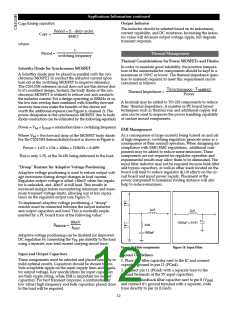
Protection and Monitoring Features
VCC1 Monitor
To maintain predictable startup and shutdown character-
istics an internal VCC1 monitor circuit is used to prevent the
part from operating below 3.75V minimum startup. The
VCC1 monitor comparator provides hysteresis and guaran-
tees a 3.70V minimum shutdown threshold.
Short Circuit Protection
A lossless hiccup mode short circuit protection feature is
provided, requiring only the soft start capacitor to imple-
ment. If a short circuit condition occurs (VFFB < 1V), the VFFB
low comparator sets the FAULT latch. This causes the top
MOSFET to shut off, disconnecting the regulator from it’s
input voltage. The soft start capacitor is then slowly dis-
charged by a 2µA current source until it reaches it’s lower
0.7V threshold. The regulator will then attempt to restart nor-
mally, operating in it’s extended off time mode with a 50%
duty cycle, while the soft start capacitor is charged with a
60µA charge current.
Trace 4 = 5V from PC Power Supply (2V/div.)
Trace 2 = Inductor Switching Node (2V/div.)
Figure 11: Startup with regulator output shorted.
If the short circuit condition persists, the regulator output
will not achieve the 1V low VFFB comparator threshold
before the soft start capacitor is charged to it’s upper 2.5V
threshold. If this happens the cycle will repeat itself until the
short is removed. The soft start charge/discharge current
ratio sets the duty cycle for the pulses (2µA/60µA = 3.3%),
while actual duty cycle is half that due to the extended off
time mode (1.65%).
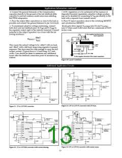
Overvoltage Protection
Overvoltage protection (OVP) is provided as result of the
normal operation of the V
2
™
control topology and requires
no additional external components. The control loop
responds to an overvoltage condition within 100ns, causing
the top MOSFET to shut off, disconnecting the regulator
from it’s input voltage. The bottom MOSFET is then acti-
vated, resulting in a “crowbar” action to clamp the output
voltage and prevent damage to the load (see Figures 12 and
13). The regulator will remain in this state until the over-
voltage condition ceases or the input voltage is pulled low.
This protection feature results in less stress to the regulator
components, input power supply, and PC board traces
than occurs with constant current limit protection (see
Figures 10 and 11).
If the short circuit condition is removed, output voltage
9

 CHERRY [ CHERRY SEMICONDUCTOR CORPORATION ]