Application Information: continued
A large negative dv/dt on the power MOSFET drain will
after a second threshold over-current condition will pri-
marily be determined by the time required to charge the
Soft Start cap from 0.275V nominal to 1.32V.
couple current into the gate driver through the gate to
drain capacitance. If this current is kept within absolute
maximum ratings for the GATE pin it will not damage the
IC. However if a high negative dv/dt coincides with the
start of a PWM duty cycle, there will be small variations in
oscillator frequency due to current in the controller sub-
strate. If required, this can be avoided by choosing the
transformer ratio and reset circuit so that a high dv/dt
does not coincide with the start of a PWM cycle, or by
clamping the negative voltage on the GATE pin with a
schottky diode
The second threshold will only be reached when a high
dv/dt is present at the current sense pin. The signal must
be fast enough to reach the second threshold before the
first threshold turns off the driver. This will normally hap-
pen if the forward inductor saturates or when there is a
shorted load.
Excessive filtering of the current sense signal, a low value
current sense resistor, or even an inductor that does not
saturate during heavy output currents can prevent the sec-
ond threshold from being reached. In this case the first cur-
rent sense threshold will trip during each cycle of high out-
put current conditions. The first threshold will limit output
current but some components, especially the output rectifi-
er, can overheat due to higher than normal average output
current.
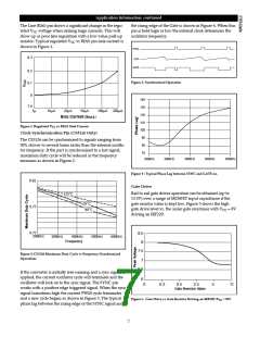
First Current Sense Threshold
During normal operation the peak primary current is con-
trolled by the level of the VFB pin (as determined by the
control loop) and the current sense network. Once the sig-
nal on the ISENSE pin exceeds the level determined by VFB
pin the pwm cycle terminates. During high output currents
the VFB pin will rise until it reaches the VFB clamp. The first
current sense threshold determines the maximum signal
allowed on the ISENSE pin before the PWM cycle is termi-
nated. Under this condition the maximum peak current is
determined by the VFB Clamp, the slope compensation
ramp, the PWM comparator offset voltage and the PWM
on time. The nominal first current threshold varies with on
time and can be calculated from Formulas (2) & (3) below.
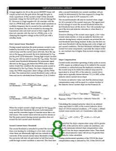
Slope Compensation
Current mode converters operating at duty cycles in excess
of 50% require an artificial ramp to be added to the current
waveform or subtracted from the feedback waveform. For
the current loop to be stable the artificial ramp must be
equivalent to at least 50% of the inductor current down
slope and is typically chosen between 75 % to 100% of the
inductor down current down slope.
To choose an inductor value such that the internal slope
compensation ramp will be equal to a certain fraction of
the inductor down current slope use the Formula (4).
CS5124
2.9V – 170mV/µs × TON
1st Threshold =
– 60mV
(2)
(3)
10
NSECONDARY
NPRIMARY
1
× (VOUT + VRECTIFIER)
×
×
Internal Ramp
CS5126
1st Threshold =
2.65V – 85mV/µs × TON
R
I(SENSE) × Slope Value Factor = Inductor Value (H)
(4)
– 125mV
5
Calculating the nominal inductor value for an artificial
ramp equivalent to 100% of the current inductor down
slope at CS5126 nominal conditions, a 5V output, a 200mΩ
When the output current is high enough for the ISENSE pin
to exceed the first threshold, the pwm cycle terminates
early and the converter begins to function more like a cur-
rent source. The current sense network must be chosen so
that the peak current during normal operation does not
exceed the first current sense threshold.
current sense resistor and a 4:1 transformer ratio yields
1
1
4
× (5V + 0.3V) ×
× 0.2Ω × 1 = 13.2 µH
20mV/µs
To check that the slope compensation ramp will be greater
than 50% of the inductor down under all conditions, sub-
stitute the minimum internal slope compensation value
and use 0.5 for the slope compensation value. Then check
that the actual inductor value will always be greater than
the inductor value calculated.
Second Current Sense Threshold
The second threshold is intended to protect the converter
from over-heating by switching to a low duty cycle mode
when there are abnormally high fast rise currents in the
converter. If the second current sense threshold is tripped,
the converter will shut off and restart in Soft Start mode
until the high current condition is removed. The dead time
During synchronized operation of the CS5126 the slope
compensation ramp is reduced by 33%. If the CS5126 will
8

 CHERRY [ CHERRY SEMICONDUCTOR CORPORATION ]