Preliminary Data Sheet
April 1999
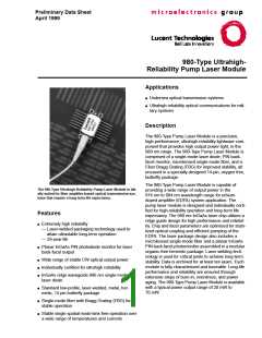
980-Type Ultrahigh
Reliability Pump Laser Module
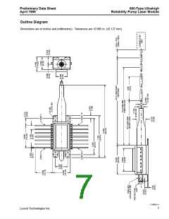
Mounting Instructions
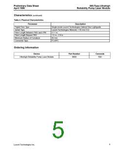
Pinout Information (continued)
The minimum fiber-bend radius is 25 mm.
Table 1. Pinout Descriptions
To avoid degradation in performance, mount the mod-
ule on the board as follows (see Figure 2):
Pin
Connection
1
2
Chassis Ground
Chassis Ground
1. Place the bottom flange of the module on a flat heat
sink at least 0.5 in. x 1.180 in. (12.7 mm x 30 mm) in
size. The surface finish of the heat sink should be
better than 32 µin. (0.8 µm), and the surface flatness
must be better than 0.001 in. (25.4 µm).
3
Photodetector Anode
Photodetector Cathode
Chassis Ground
4
5
6
Chassis Ground
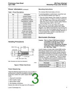
Mount four #2-56 screws with Fillister heads (M2-
3 mm) at the four screw hole locations (see Outline
Diagram). The Fillister head diameter must not exceed
0.140 in. (3.55 mm). Do not apply more than 2 in./lb. of
torque to the screws. To minimize package distortion, it
is recommended that a washer is used above and
beneath each mounting foot.
7
Chassis Ground
8
Chassis Ground
9
Chassis Ground
10
11
12
13
14
Pump Laser Anode
Pump Laser Cathode
Chassis Ground
Chassis Ground
Electrostatic Discharge
Chassis Ground
Caution: This is a Class 0 ESD device which is
susceptible to damage as a result of
electrostatic discharge (ESD). Take
proper precautions during both handling
and testing. Follow JEDEC Publication
No. 108-A (Dec. 1998).
Handling Precautions
0.118
(3.00)
0.062 (1.58)
0.031 (0.79)
0.086
(2.18)
Lucent employs a human-body model (HBM) and the
field-induced charged-device model (CDM) for ESD-
susceptibility testing and protection design evaluation.
ESD voltage thresholds are dependent on the critical
parameters used to define the model. A standard HBM
(resistance = 1.5 kΩ, capacitance = 100 pF) is widely
used and, therefore, can be used for comparison pur-
poses. The HBM ESD threshhold presented here was
obtained using these circuit parameters:
0.140
(3.56)
0.129 (3.28)
0.041 (1.04)
Note: Dimensions are inches and (millimeters).
1-532(F)
Parameter
Value
Unit
Charged-device Model
Human-body Model
≥200
≥400
V
V
Figure 2. Fillister Head Screw
Power Sequencing
Adopt the following sequence for turn-on as a matter of
good practice to avoid the possibility of damage to the
pump laser module from power supply switching tran-
sients:
1. All ground connections
2. Most negative supply
3. Most positive supply
4. All remaining connections
Reverse the order for the proper turn-off sequence.
3
Lucent Technologies Inc.

 AGERE [ AGERE SYSTEMS ]